Why Choose a Torque Control Gear Motor?
A Torque Control Gear Motor combines mechanical reduction with adjustable torque management. This pairing matters when machines must start smoothly, hold loads, and avoid sudden movement. Conveyor belts, packaging lines, lifting systems, and automated tools often depend on these qualities. The motor does not merely produce rotation. It delivers usable force at a controlled speed.
Gear-design authority Darle W. Dudley described the practical purpose of gearing simply: “A gear train is a torque and speed converter.” That principle remains relevant in modern motor selection. A gearbox can multiply output torque, while control electronics regulate acceleration and load response. The result is steadier operation, lower mechanical stress, and better process consistency.
Small details matter. A properly selected unit can prevent belt slipping during startup. It can also reduce impact noise near a machine operator. Engineers must match rated torque, peak torque, gear ratio, duty cycle, and thermal limits. Ignoring one factor can create expensive problems. Sometimes, a larger motor is not the best answer.
Real installations are rarely perfect. Misalignment, temperature changes, and uneven loading can affect performance. Therefore, selection should include testing under realistic conditions. Measure the load. Observe the startup. Check the housing temperature. These steps reveal weaknesses that catalog figures may hide.
This guide explains why a Torque Control Gear Motor can improve control, reliability, and long-term equipment performance. It also examines where this technology may fall short. That honest comparison supports a better engineering decision.
What Is a Torque Control Gear Motor?
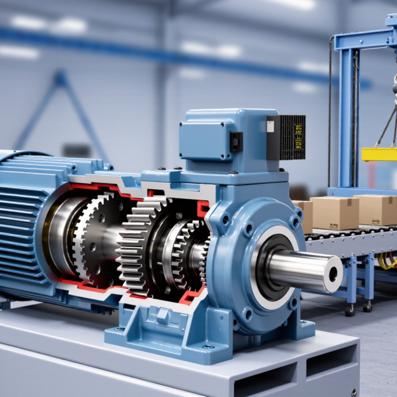
A torque control gear motor combines an electric motor, gearbox, and control system. The gearbox reduces speed and increases usable output torque. The controller then regulates that torque during changing loads. On a conveyor, for example, it can maintain steady pulling force when boxes accumulate. On an auger, it can react before material blockage causes severe stress.
This matters because motor-driven systems consume an estimated 53% of global electricity, according to the International Energy Agency. The U.S. Department of Energy also reports that motor systems use about 70% of industrial electricity. Better torque management can reduce mechanical shock, unnecessary current, and heat. It may also extend coupling and bearing life. Small details matter.
In practical operation, sensors measure current, position, or rotational speed. The drive compares those signals with the required torque. It then adjusts motor power within milliseconds. A suitable gear ratio remains essential. Incorrect sizing can create sluggish starts, excessive noise, or rapid thermal buildup. Torque control is not magic. Poor tuning still wastes energy. Some installations also overlook gearbox efficiency, which weakens the expected gains. Engineers should review peak load, duty cycle, start frequency, and braking needs before selecting the motor. Industry testing often focuses on rated output, but real machines rarely operate at one constant load. That gap deserves closer attention.
| Data Dimension | Typical Specification or Characteristic | How It Supports Torque Control | Typical Engineering Consideration |
|---|---|---|---|
| Definition | A geared electric motor system designed to regulate or maintain output torque at the driven shaft. | The motor, gearbox, controller, and feedback device work together to deliver a controlled turning force. | Torque control is different from speed control; a system may require one or both functions. |
| Main Components | Electric motor, reduction gearbox, motor controller, torque feedback or estimation system, and mechanical output shaft. | The gearbox increases available output torque while the controller adjusts motor current and operating conditions. | Component compatibility, thermal capacity, backlash, and shaft loading must be checked as a complete system. |
| Torque Control Method | Current-based control, closed-loop torque control, or torque control using a load cell or torque transducer. | Motor torque is closely related to motor current, while a sensor-based loop can correct for mechanical losses and disturbances. | Sensorless estimation is simpler; direct measurement generally provides better accuracy and load verification. |
| Output Torque | Specified in newton-metres (N·m). The available value depends on motor power, gearbox ratio, efficiency, and duty cycle. | A reduction gearbox trades speed for torque, allowing a smaller, faster motor to drive a higher-torque load. | Do not select only by peak torque; continuous torque, starting torque, and shock loads are also important. |
| Gear Ratio | Common industrial gear reductions range from low single-digit ratios to several hundred to one, depending on the gearbox type. | Higher ratios generally increase output torque and reduce output speed. | High ratios can increase backlash, reduce efficiency, and limit the maximum output speed. |
| Speed Range | Output speed is determined by motor speed divided by the gear ratio; many applications operate from low rpm to several hundred rpm. | Torque control can maintain the required load force while the drive adjusts speed within the motor and gearbox limits. | Confirm the minimum stable speed, maximum permissible speed, and acceleration requirements. |
| Torque Accuracy | Accuracy varies widely. Sensor-based systems can typically achieve tighter control than open-loop or basic current-estimation systems. | Feedback compensates for changes caused by friction, temperature, supply voltage, and load variation. | The final accuracy depends on sensor quality, calibration, gearbox friction, backlash, and controller tuning. |
| Continuous and Peak Load | Continuous torque is the permissible long-duration load; peak torque is available for a limited time during starting or acceleration. | The controller can limit current to protect the motor and gearbox from overload. | Peak ratings must include a specified time limit and duty cycle; continuous overload can cause overheating. |
| Motor Types | Common options include brushed DC, brushless DC, AC induction, and permanent-magnet synchronous motors. | Each motor type offers different torque response, maintenance needs, efficiency, and controller requirements. | Brushless and AC systems are often preferred for demanding continuous-duty applications, while brushed DC can simplify basic systems. |
| Efficiency | Overall efficiency is the product of motor, controller, and gearbox efficiencies; it is always lower than the efficiency of the motor alone. | Efficient torque transmission reduces heat generation and electrical energy consumption. | Worm gearboxes can provide high reduction in a compact form but may have lower efficiency than many helical or planetary designs. |
| Backlash | Backlash is the angular movement between mating gear teeth when the direction of torque changes. | Low-backlash gearing improves positioning and reversing performance under controlled torque. | Planetary and precision gearboxes may offer lower backlash, while standard gearboxes are often selected for cost-sensitive applications. |
| Protection and Safety | Typical protective functions include overcurrent, overtemperature, stall, short-circuit, and overvoltage protection. | Torque limits can help prevent mechanical damage, jam-related current spikes, and excessive stress on the driven equipment. | A torque limit is not a substitute for guarding, emergency stopping, mechanical brakes, or a properly designed safety circuit. |
| Thermal Management | Heat is generated by motor losses, controller losses, and gearbox friction, especially during low-speed high-torque operation. | Monitoring temperature helps maintain consistent torque and prevents insulation or lubricant damage. | Evaluate ambient temperature, enclosure ventilation, mounting conditions, duty cycle, and allowable winding temperature. |
| Control Interface | Common interfaces include analog voltage or current, pulse and direction, digital inputs, and industrial communication networks. | The interface allows the machine controller to command torque, speed, direction, enable status, and fault reset. | Confirm signal resolution, response time, electrical isolation, communication protocol, and fault-handling behavior. |
| Energy Consumption | Power demand is approximately related to torque and angular speed: mechanical power equals torque multiplied by angular velocity. | The drive supplies only the current needed for the required load and acceleration profile. | Energy savings are greatest when the application frequently operates below maximum load or requires variable speed. |
| Typical Applications | Conveyors, mixers, winding equipment, feeders, valve actuators, lifting mechanisms, packaging machines, and material-handling systems. | Controlled torque helps manage tension, prevent product damage, regulate feeding force, and handle variable loads. | Application selection should consider load inertia, direction changes, shock loads, holding requirements, and environmental conditions. |
| Key Selection Formula | Required output torque should include load torque, acceleration torque, friction torque, and a suitable service factor. | Correct sizing prevents nuisance trips and maintains stable torque under the full operating cycle. | Verify: Trequired ≈ (Tload + Tacceleration + Tfriction) × service factor. |
| Why Choose This Configuration? | It provides controlled force, smooth starting, overload management, repeatable operation, and flexible speed-torque performance. | The integrated motor-and-gearbox arrangement delivers high torque in a compact package while the controller manages the operating point. | It is most beneficial when the process requires predictable load force rather than simple fixed-speed rotation. |
Note: Actual torque, speed, accuracy, efficiency, and duty-cycle values depend on the selected motor, gearbox, controller, feedback device, supply voltage, and application load. Always verify the manufacturer’s technical documentation and perform application-specific sizing.
It combines an electric motor, gearbox, and control system. The gearbox lowers speed and increases usable torque. The controller adjusts force as the load changes.
Sensors measure current, position, or rotational speed. The drive compares these signals with the required torque. It adjusts motor power within milliseconds. Fast response helps.
They suit conveyors, mixers, packaging machines, lifting systems, and valve actuators. A conveyor may keep pulling steadily when boxes accumulate. A mixer may handle changing resistance more smoothly.
It can reduce sudden overloads when materials shift or resistance rises. This may protect couplings, bearings, and connected equipment. It cannot fix poor sizing or bad alignment.
Review peak load, duty cycle, start frequency, gear ratio, and braking needs. Consider real operating loads, not only the rated output. Machines rarely run at one constant load.
Better torque management can reduce unnecessary current, mechanical shock, and heat. The result depends on gearbox efficiency and controller tuning. The savings are not automatic.
Listen for clicking, humming, or unusual vibration. Check oil leaks, loose bolts, housing temperature, vents, cables, and terminals. Use the specified lubricant. Too much grease can also cause trouble.
Record operating temperature, noise changes, and inspection dates. Compare readings over time, rather than trusting memory. A loose mounting bolt can resemble motor failure. That mistake is costly, but easy to understand.
Isolate power before opening covers or touching connections. Keep vents clear near dusty equipment. Recheck torque settings after installation. Small details matter.
A Torque Control Gear Motor combines a gear reduction system with adjustable torque regulation, allowing machinery to deliver controlled force at a stable speed. Its torque control technology monitors and adjusts motor output according to changing loads, helping prevent overloads, sudden movement, and unnecessary energy consumption. This makes it valuable in industrial applications that require accurate positioning, smooth starts, consistent pressure, or reliable operation under variable working conditions.
When choosing a Torque Control Gear Motor, users should consider required torque, operating speed, load characteristics, duty cycle, installation space, control compatibility, efficiency, and environmental conditions. Common uses include conveyors, lifting equipment, packaging machinery, automated production lines, mixers, and material-handling systems. Regular maintenance should include checking lubrication, inspecting gears and couplings, monitoring temperature and vibration, tightening connections, and replacing worn components when necessary. Selecting the correct motor and following a practical maintenance schedule can improve equipment performance, safety, and service life.

 Syncdrive Motor