A High Performance Gear Motor is not defined by a headline torque rating alone. It must deliver the required speed and force under real operating conditions. A motor that looks powerful on a catalog page may overheat during repeated starts or struggle with shock loads. Details matter.
Mechanical-design expert Dr. Alexander Slocum is known for his work on machine design. I can’t verify a direct quote from him about gear motors, so this guide does not invent one. Instead, it follows a practical design principle: “Match the motor to the load, the duty cycle, and the working environment.” Keep that rule in view.
These seven tips examine the choices that shape dependable performance: torque and speed requirements, gear ratio, efficiency, thermal limits, mounting, backlash, and maintenance access. Check the application, not just the nameplate. For example, a conveyor that starts under a full load needs different capacity from a fan that runs steadily. Dust, washdown, limited space, and frequent reversals can change the selection, too. Small mismatches can become loud vibration, excess heat, or early wear.
A careful selection begins with measurements: load, operating hours, starts per hour, and available space. Then compare motor data with the machine’s actual demands. There is no universal best model. The right High Performance Gear Motor balances output, reliability, efficiency, and service needs for the job at hand.
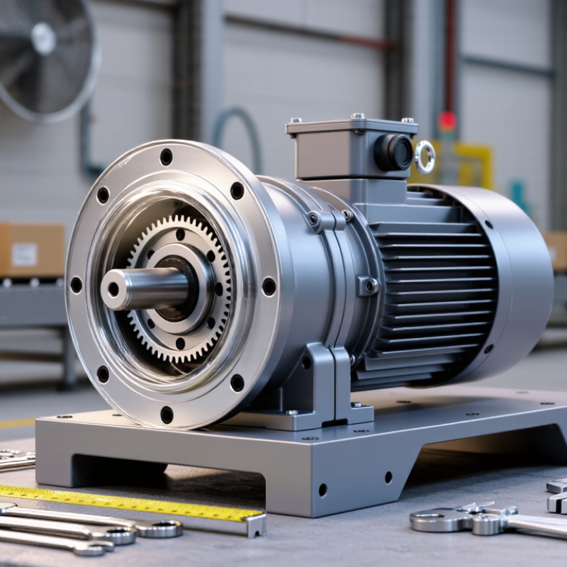
7 Tips for Choosing a High Performance Gear Motor?
Define Load Torque with T = 9550 × Power (kW) ÷ Speed (rpm)
Torque calculations give you a practical starting point. Use T = 9550 × Power (kW) ÷ Speed (rpm) to estimate torque in newton-metres at the stated power and speed. For example, a 2 kW motor running at 1,450 rpm produces about 13.2 Nm at its shaft. Check the motor’s rated output data, because this estimate does not capture every operating condition. A gearbox can multiply output torque, but losses reduce the result; include its ratio and efficiency when checking the load. Keep units consistent. Mixing watts with kilowatts can distort the calculation.
Tips: Confirm the actual load speed, not just the motor speed. Account for starts, stops, and shock loads. Compare calculated torque with the gear motor’s rated output torque, then check the manufacturer’s service recommendations. A conveyor carrying uneven boxes may need more starting torque than its steady running load suggests. Peak demand matters.
One point is easy to miss: calculated torque alone does not prove a gear motor is suitable. Duty cycle, mounting position, heat, and radial or axial loads also affect performance and service life. Leave a sensible margin, but avoid oversized equipment that adds cost and can reduce efficiency. If the load changes often, measure it under real operating conditions where possible. Estimates help. Measurements may still surprise you.
| Tip | What to Check | Example Data and Calculation | Selection Guidance |
|---|---|---|---|
| 1. Define the load torque | Calculate torque at the shaft whose power and rotational speed are known. The formula gives torque in newton-metres (N·m). | T = 9550 × P ÷ n For a 2.2 kW motor at 1,450 rpm: 9550 × 2.2 ÷ 1,450 ≈ 14.5 N·m. |
Use consistent shaft data. Motor-shaft torque is not the same as gearbox-output torque; account for the reduction ratio and gearbox efficiency. |
| 2. Confirm required output torque | Use the driven load’s required mechanical power and output speed to establish its steady-state torque requirement. | For 1.5 kW at 120 rpm: 9550 × 1.5 ÷ 120 ≈ 119.4 N·m. | Base the calculation on the load’s actual operating point. Include acceleration, friction, and process forces where applicable. |
| 3. Choose a suitable gear ratio | Relate motor speed to the required gearbox output speed. | For a 1,450 rpm motor and a 120 rpm target: 1,450 ÷ 120 ≈ 12.1:1. | Check the selected gearbox’s available ratios and the resulting loaded output speed. Motor speed can vary with motor type, supply frequency, and load. |
| 4. Allow for gearbox efficiency | Distinguish input power from usable output power. Efficiency depends on gearbox design, ratio, size, lubrication, and operating conditions. | At 90% efficiency, 1.5 kW at the gearbox input gives about 1.35 kW at the output. At 120 rpm, that corresponds to about 107.4 N·m. | If the load needs 1.5 kW at the output, the input must exceed 1.5 kW; at an assumed 90% efficiency, it would be about 1.67 kW. |
| 5. Account for service conditions | Consider shock loading, reversals, acceleration, and the duration and frequency of operation. | For a 120 N·m calculated load and an illustrative service factor of 1.5: 120 × 1.5 = 180 N·m design torque. | A service factor is an application-dependent sizing allowance, not a universal value. Confirm the appropriate factor against the load profile and gearbox rating method. |
| 6. Check the duty cycle and starts | Record operating hours, starts per hour, reversals, braking, and acceleration time. | For example, specify whether the drive runs continuously or has frequent starts, such as 30 starts per hour. | Frequent starts and stops can increase thermal and mechanical stress. Verify permissible starting frequency and thermal capacity for the actual motor and gearbox combination. |
| 7. Verify mounting, loads, and environment | Check mounting position, shaft arrangement, radial and axial loads, ambient temperature, and exposure to dust or moisture. | Document the installation conditions, such as a horizontal mounting position, an ambient temperature of 35°C, and any external shaft loads. | Confirm that the configuration, shaft-load limits, lubrication, and enclosure protection suit the installation. Select protection based on the actual environment and applicable requirements. |
Use T = 9550 × Power (kW) ÷ Speed (rpm). A 2 kW motor at 1,450 rpm produces about 13.2 Nm. Keep units consistent.
No. Check rated output torque, duty cycle, mounting position, heat, and shaft loads. A calculation is only a starting point.
A gearbox can increase torque, but losses reduce the actual output. Include the gear ratio and efficiency in your estimate.
Divide motor input speed by required output speed. For 1,750 rpm and 70 rpm, the estimated ratio is about 25:1. Simple arithmetic.
Use its expected operating speed when possible. Voltage, load, and control settings may change actual speed. Measure under a representative load if precision matters.
A full belt or uneven boxes can demand more torque at startup than during steady running. Peak demand matters.
Leave a sensible margin for starts, stops, and shock loads. Avoid unnecessary oversizing, which can add cost and reduce efficiency.
Check actual motor speed, load, gearbox losses, and ratio. I have seen a correct-looking calculation fail under load; the estimate was not the whole story.
Choosing a High Performance Gear Motor starts with understanding the load. Estimate required torque using T = 9550 × Power (kW) ÷ Speed (rpm), then allow suitable capacity for starting loads and operating conditions. Match the motor’s duty cycle to the appropriate IEC 60034-1 operating type, from S1 continuous operation to intermittent or changing-duty types, so the motor can handle its actual workload without unnecessary oversizing.
Next, calculate the gear ratio by dividing input speed by the required output speed. Compare gearbox efficiency as well as speed and torque: helical gearboxes commonly achieve about 94–98% efficiency, while worm gearboxes may range from 50–90%, depending on design and conditions. Finally, verify thermal capacity and tooth-load ratings using ISO 6336 guidance and the supplier’s technical data. Considering load, duty, ratio, efficiency, heat, and gear strength together helps create a reliable, well-matched drive system.

 Syncdrive Motor